|
Subsections
- Unified Modeling Language - UML.
- A modeling language, not a method.
- Provides a graphical representation that allows developers and architects to model a software system before the system is ever built.
- Analogy - an architect creating a blueprint before a house or office building is ever built.
- The UML does not specify a methodology/process. Therefore, saying ``We use the UML methodology is incorrect.''
A few URLs for reference:
- http://www.omg.org
- http://www.rational.com/uml/index.jsp
- UML Distilled - http://www.awl.com/cseng/titles/0-201-32563-2
The UML defines nine standard diagrams:
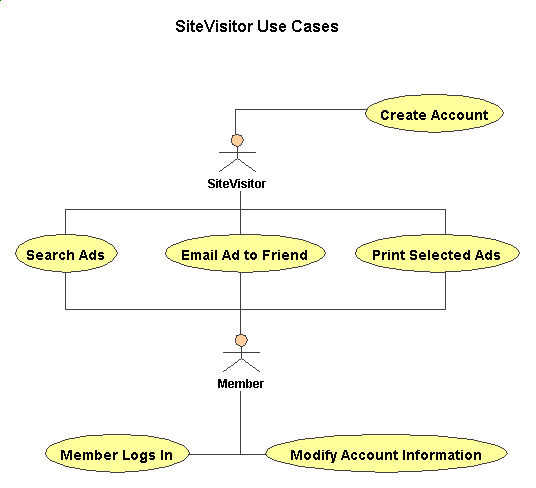
- Use Case
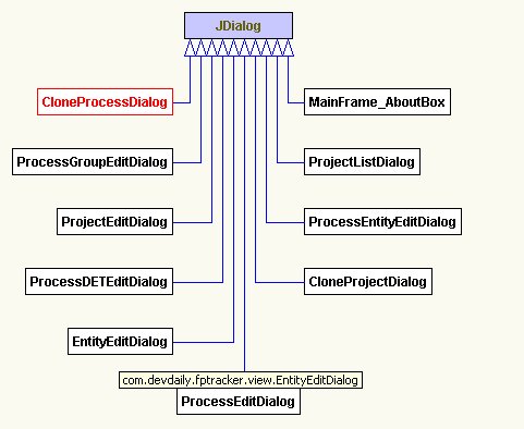
- Class
- Interaction
- Sequence
- Collaboration
- Package
- State
- Activity
- Component
- Deployment
Note that the UML can be used to model other processes besides software development.
A typical interaction between a user and a computer system.
Figure 1.1:
A sample UML Use Case Diagram.
|
|
- Describes the types of objects in the system, and the static relationships between them.
- Two main kinds of static relationships:
- Associations - Has-A
- Subtypes - Is-A
Figure 1.2:
A high level class diagram showing the relationships between classes.
|
|
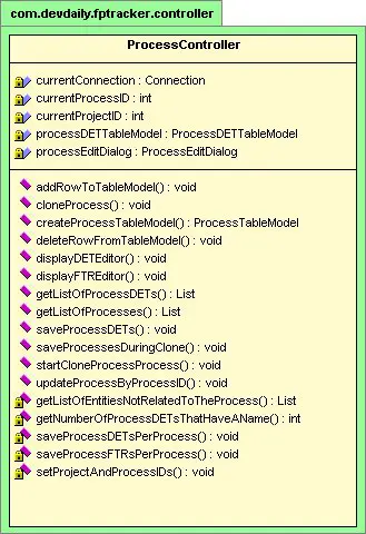
Figure 1.3:
A class diagram showing the detailed attributes and behaviors of a class.
|
|
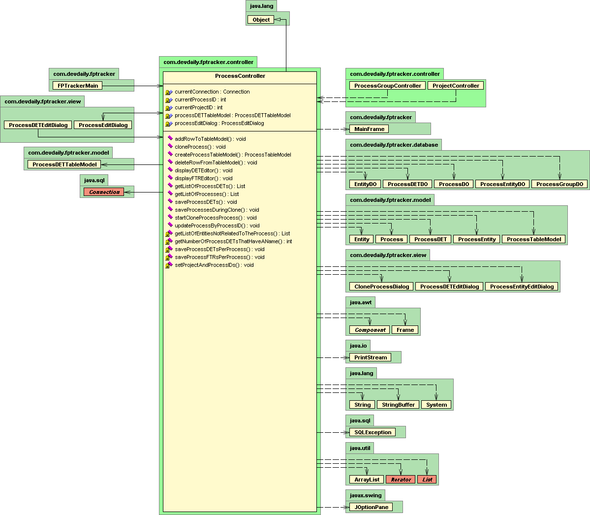
Figure 1.4:
A class diagram showing relationships to classes in other packages
|
|
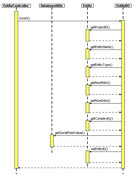
- Sequence diagrams follow the flow of entire use cases (emphasis on time ordering).
- One sequence diagram for the basic course and alternative courses for each of your use cases.
Figure 1.5:
A sequence diagram follows the flow of an entire use case.
|
|
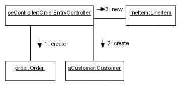
- Shows how critical objects collaborate within a use case.
- Similar to sequence diagrams.
- Focus on key transactions.
- Sequence diagrams follow the flow of entire use cases (emphasis on time ordering).
- Collaboration diagrams add extra detail related to timing of messages.
Figure 1.6:
A collaboration diagram shows how important objects collaborate within a use case.
|
|
- Classes are arranged into logically-ordered packages.
- Package diagrams show relationships and dependencies between packages.
- Package diagrams are vital for large projects.
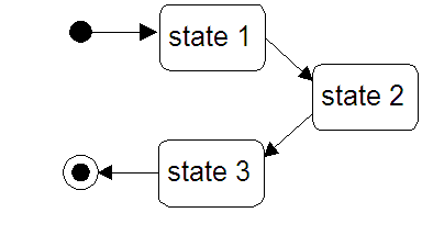
- Captures the lifecycle of one or more objects.
Figure 1.7:
A state diagram captures the lifecycle of one or more objects.
|
|
- Advanced flowcharts.
- Swimlanes let you organize a set of activities according to who is performing them.
- The implementation view of a system.
- Displays the organization and dependencies between software components.
- The environment view of a system.
- Shows the physical relationships among software and hardware components.
- Each node represents some computational unit - usually a piece of hardware.
- Connections show communication paths.
- In practice probably not used very much, though most projects have a drawing that looks something like these.
|
|